Public Archive This website won't be receiving any further updates, but will be left up in the hopes that someone may find it useful (here's the source code). Thanks to everyone who made this possible, and maybe see y'all again next year! -Colin & Titus
DIY Loudspeaker
Introduction
Today, you will make a loudspeaker! It’s surprisingly simple, and requires just three parts:
- a coil of wire
- a permanent magnet
- an acoustic transducer to convert magnetic force to sound
Combined with a source of music (such as a computer or mobile phone) and an amplifier (which we will provide), you will have a complete sound system!
Overview
Sound is created by vibrations of mechanical structures at audio frequencies, which induce motions (and ultimately pressures) in the air. Musical instruments use many different types of vibrating structures, including strings, reeds, soundboards, and drumheads. Loudspeakers create sounds from electrical signals. They typically contain an electromechanic transducer that converts an electrical signal to a mechanical force, and an acoustic transducer that converts the mechanical force to sound.
Electric Field to Mechanical Force Transduction
Electric current to mechanical force transduction. An electromagnet transduces electrical current into a magnetic field. By combining an electromagnet with a permanent magnet, mechanical force can be generated. Typically a helical coil of wire called a solenoid is used to focus the induced electromagnetic field for maximum force generation.
Mechanical Force to Acoustic Wave Transduction
Vibrations of the strings of a violin generate forces that are coupled to the body of the violin, which acts as a soundboard, and launches sound. Commercial loudspeakers generally employ diaphrams that move like a piston to make sound.
Electromagnetic Transduction
Primer on Current
In conventional English, a circuit is a path or route that starts at one place and ultimately returns to that same place. The engineering sense of the word is similar. In electronics, a circuit is a closed path through which electrical currents can flow. The flow of electrical current through a flashlight illustrates the idea.

Three parts of the flashlight comprise the circuit: the battery, which supplies power, a bulb, which produces light when connected to the battery, and a switch, which can either be on (connected) or off (disconnected). The important feature of this circuit is that electrical currents flow through it in a loop, as illustrated in the right part of the figure above.
Primer on Magnetic Field
As current passes through a wire, it generates a magnetic () field. The magnetic field encircles the wire in a direction given by the right-hand rule, and the strength of the field decreases with distance from the wire.
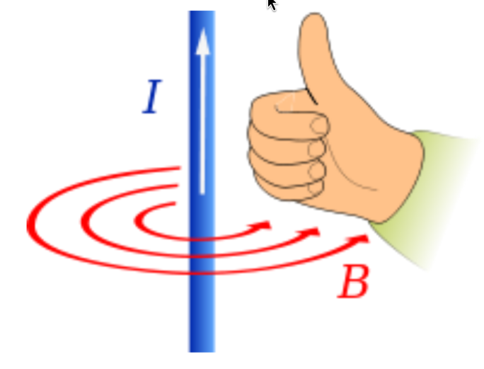
Like electrical current, the magnetic flux (which is represented by the field) flows in loops. However, unlike electrical current, which requires specialized conductors (e.g., wires), the magnetic flux can flow through air. Furthermore, the magnetic flux from one part of the wire can interact (and sum) with that from other parts. Using this idea, we can generate a strong magnetic field by winding a wire into a helix to form a solenoid.

The magnetic fields associated with each turn of the solenoid sum so that the strength of the field in the center of the solenoid tends to increase as the number of turns increases.
Building the Electromagnetic Transducer
We will use a solenoid as an electromagnet. A large number of windings is required to get a large magnetic force. To minimize the size of the solenoid, we will use a narrow gauge magnet wire, which has a copper conductor surrounded by an insulating polymer (this stops current from passing through touching wires).
In addition to passing the electrical current required to generate a magnetic force, this wire will also introduce electrical resistance. We can take advantage of this resistance to match the electrical properties of the solenoid to those of the audio amplifier that we will use to drive the solenoid. Our (and by our, we mean Prof. Dennis Freeman’s, shoutout to him for the lab materials btw) audio amplifiers (Lepai LP-2020A+) are designed to be used with (with margin for error) speakers. Thus we can choose the length of magnet wire so that the electrical resistance of the solenoid is . We have supplied 32 gauge magnet wire, which has a resistance of approximately per 1000ft. Therefore, you should use approximately 50ft of this wire to get the desired resistance. This will correspond to 250-400 turns, depending on the diameter of your windings.
You can wind your solenoid on a paper core as shown below. Generally, using a 1/2” diameter works well. You can use tape to hold the paper core together.
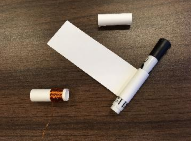
When you have finished winding, secure the turns so that they do not fall off the core. Simply twisting the wires together works well.
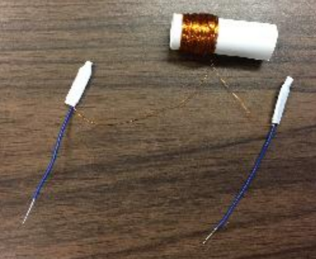
Connect a short piece (approximately 4in) of hook-up wire to each lead of your solenoid, as follows. Strip the ends of the hook-up wires so that about 0.75in of bare wire is exposed. Twist the last inch of one of the solenoid wires around the bare end of one of the hookup wires. Slide a wire crimp (DOLPHIN) over the twist and crimp with pliers.

Connect the second piece of hook-up wire as you did the first, so that the exposed ends of the hook-up wires provide electrical connections to the solenoid.
Use a multimeter to check the resistance of your coil. If the resistance is less than , find a counselor.
Multimeters are a versatile tool, capable of measuring voltage, current, and resistance. Today, we’re only interested in the latter, so to enable resistance detection, rotate the knob to , as pictured below.
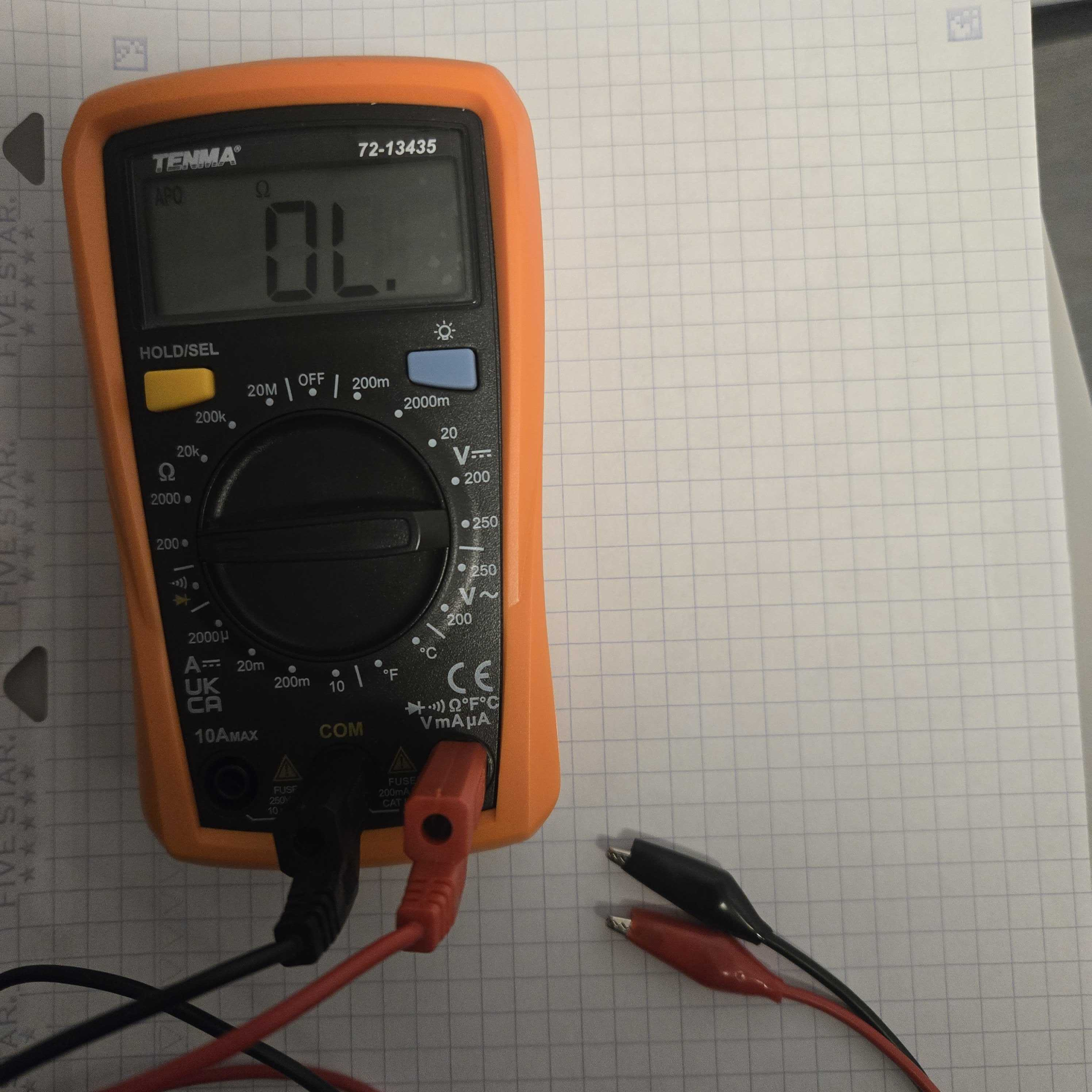
From there, connect the black and red alligator clips to the exposed wires. For resistance, it does not matter which goes to each wire. On the screen, you will hopefully see something within an order magnitude of , but if not, and after making sure the cables are in the right socket as pictured, call a counselor at this point.
Testing the Electromagnetic Transducer
Momentarily touch your leads to a 9V battery to provide power to the electromagnet. Notice that the coil gets warm. Disconnect the battery if the coil gets hot.
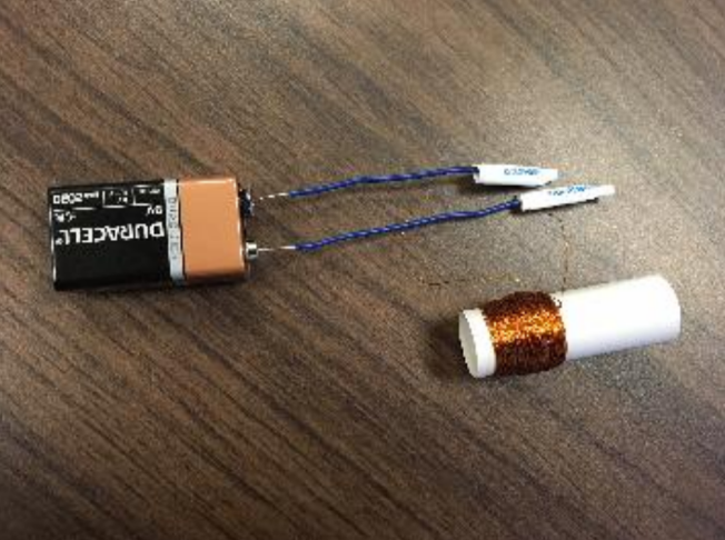
Move the electromagnet near one of your permanent magnets. You should feel a magnetic force when the battery is connected. Test the magnetic force generated by the solenoid on a permanent magnet and on a similarly shaped pellet of steel (provided).
Talk with people at your table about what happens. Try reversing the terminals. What happens when you put the magnet inside the paper? Between the magnets and the steel, what produces a stronger force (this will be important for making a speaker)?
Connecting the Amplifier
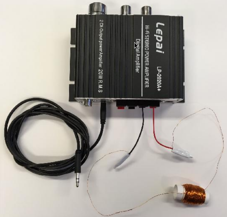
Cut and strip the wires to the battery clip so that the wires can be inserted into the amplifier. Measure the resistance of your solenoid with the multimeter. The resistance should be or greater. If the resistance is less than , see an instructor to potentially get suitable current limiting resistors to wire in series with your solenoid.
Make sure that the amplifer is switched off. Connect your solenoid to the amplifier as shown in the figure below. Connect the phone jack to a music source, and adjust the amplifier volume to be no greater than half maximum. Plug in the AC power cable. Check your connections, and then turn on the amplifier. The solenoid should get warm but not hot.
Acoustic Transducer
The quality and efficiency of acoustic transduction depends on the size and shape of the transducer as well as properties such as the stiffness of the material from which it is made. Good designs generate distortion-free sounds at low and high intensities over a wide range of frequencies.
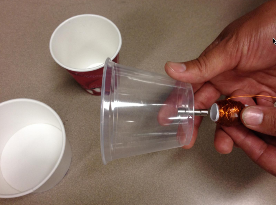
Try a variety transducers by pressing the permanent magnet(s) against a variety of surfaces (including a cup, a sheet of paper, and whatever else you can find) and then moving the solenoid close to the permanent magnet(s), as shown in the following figure.
Find a friend, and discuss the following. Maybe find a counselor too. Also take a picture (it lasts longer) to send home, if you like.
- What were the effects of size and shape of the acoustic transducer on loudness, bass, treble, and distortion.
- What were the limitations of each type of transducer you tried. Which transducer worked best?
- What effect will this have on Lebron’s legacy?
Congrats, you’re done!