Public Archive This website won't be receiving any further updates, but will be left up in the hopes that someone may find it useful (here's the source code). Thanks to everyone who made this possible, and maybe see y'all again next year! -Colin & Titus
Tools of the Trade Pt. 1
As we mentioned yesterday, now that you’re equiped with knowledge of voltage and resistance, along with the ability to play FE!N from a paper plate, you can start using the tools that make up electrical engineering.
Revisting Multimeters
Multimeters, while capable of quite a lot, have three features of note that we’ll introduce today: voltage measuring, resistance measuring, and continuity detection.
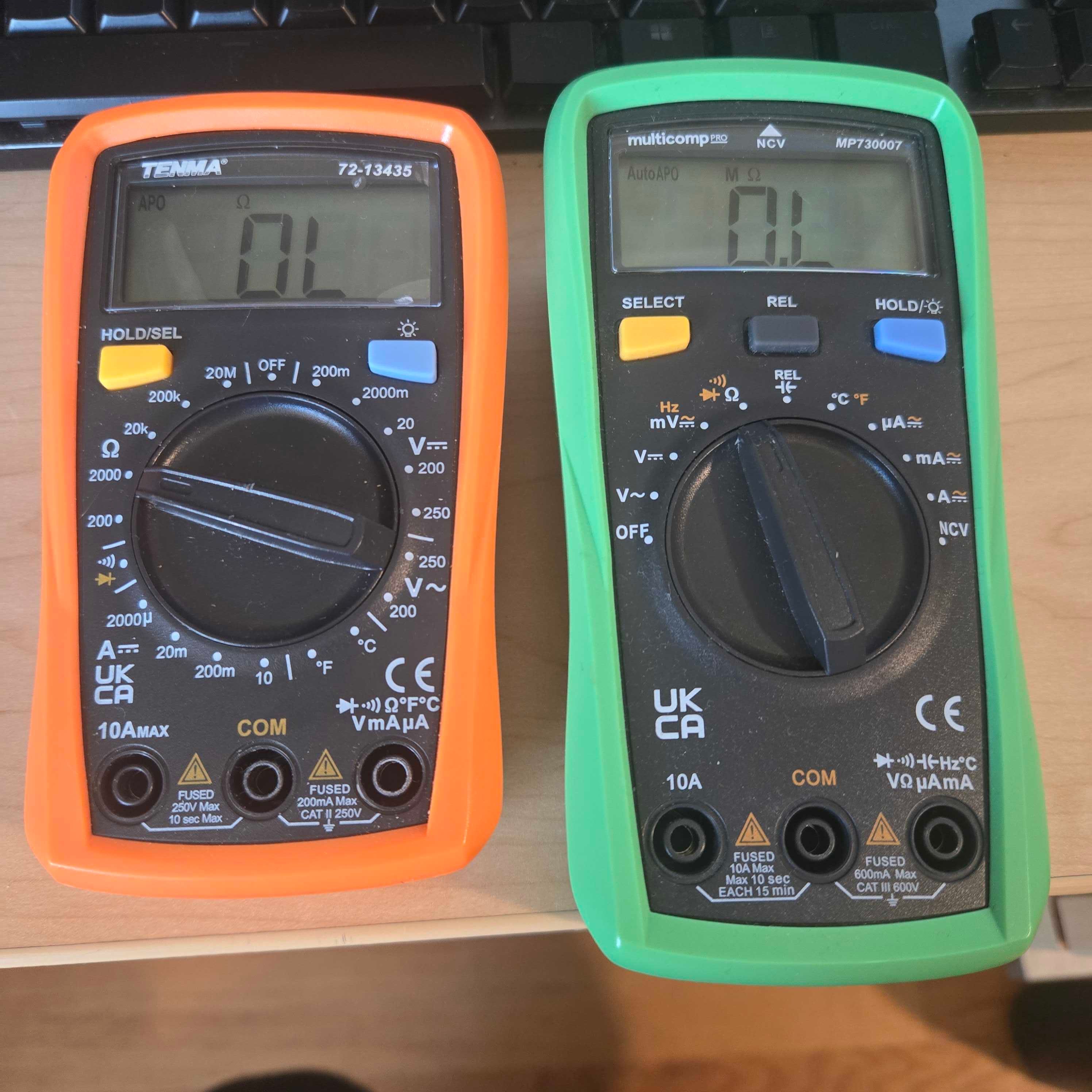
As pictured above, both multimeters are ready to measure resistance. This is useful for checking the resistance of resistors, gauging the inherent resitance of materials, and checking series and parallel combinations of resistors.
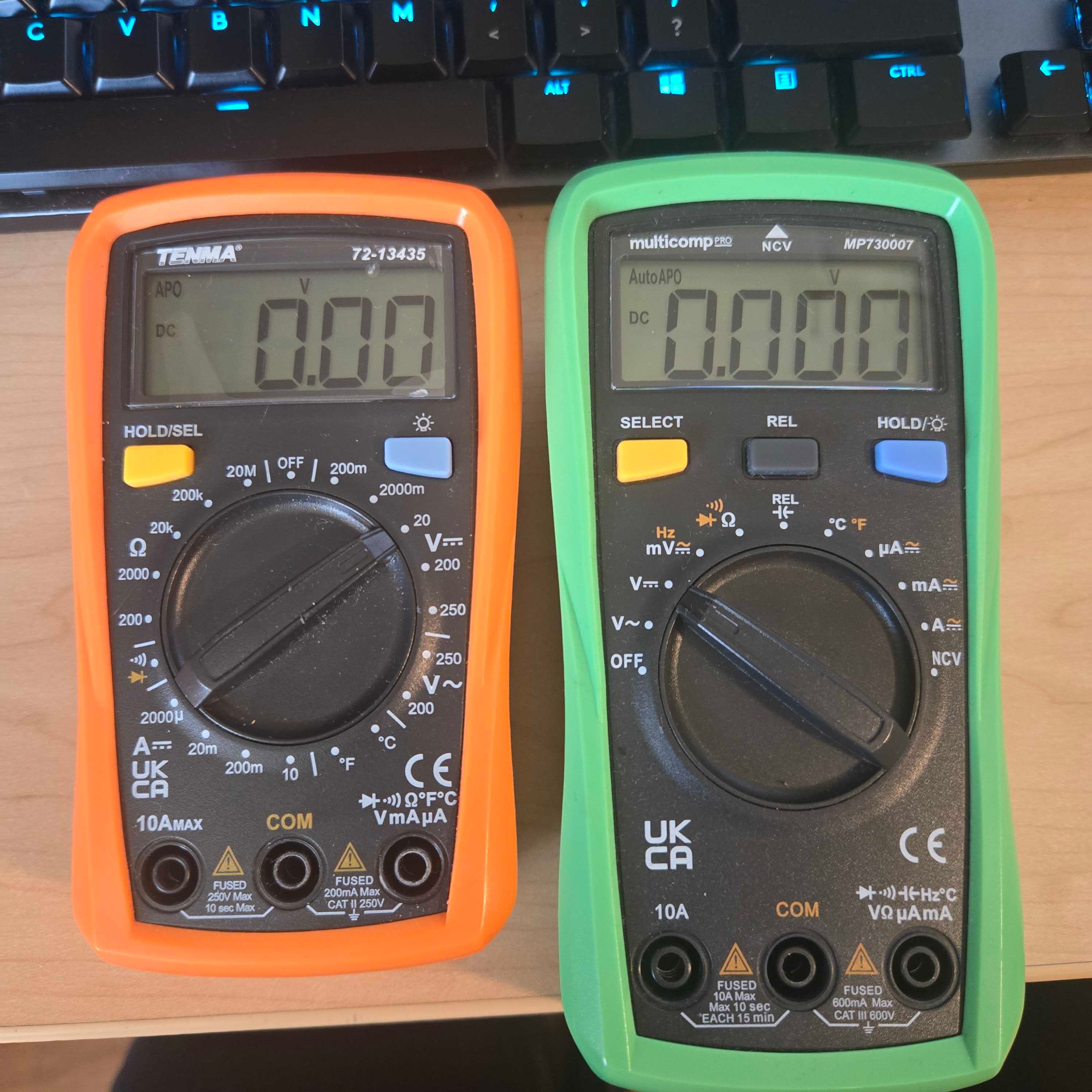
In the picture above, both multimeters are measuring voltage this time. Attaching the leads to the two ends of a component (or multiple components) in a circuit reveal the voltage drop across it/them, which is useful for determining relative voltages (as “ground” can be wherever you like), among other things.
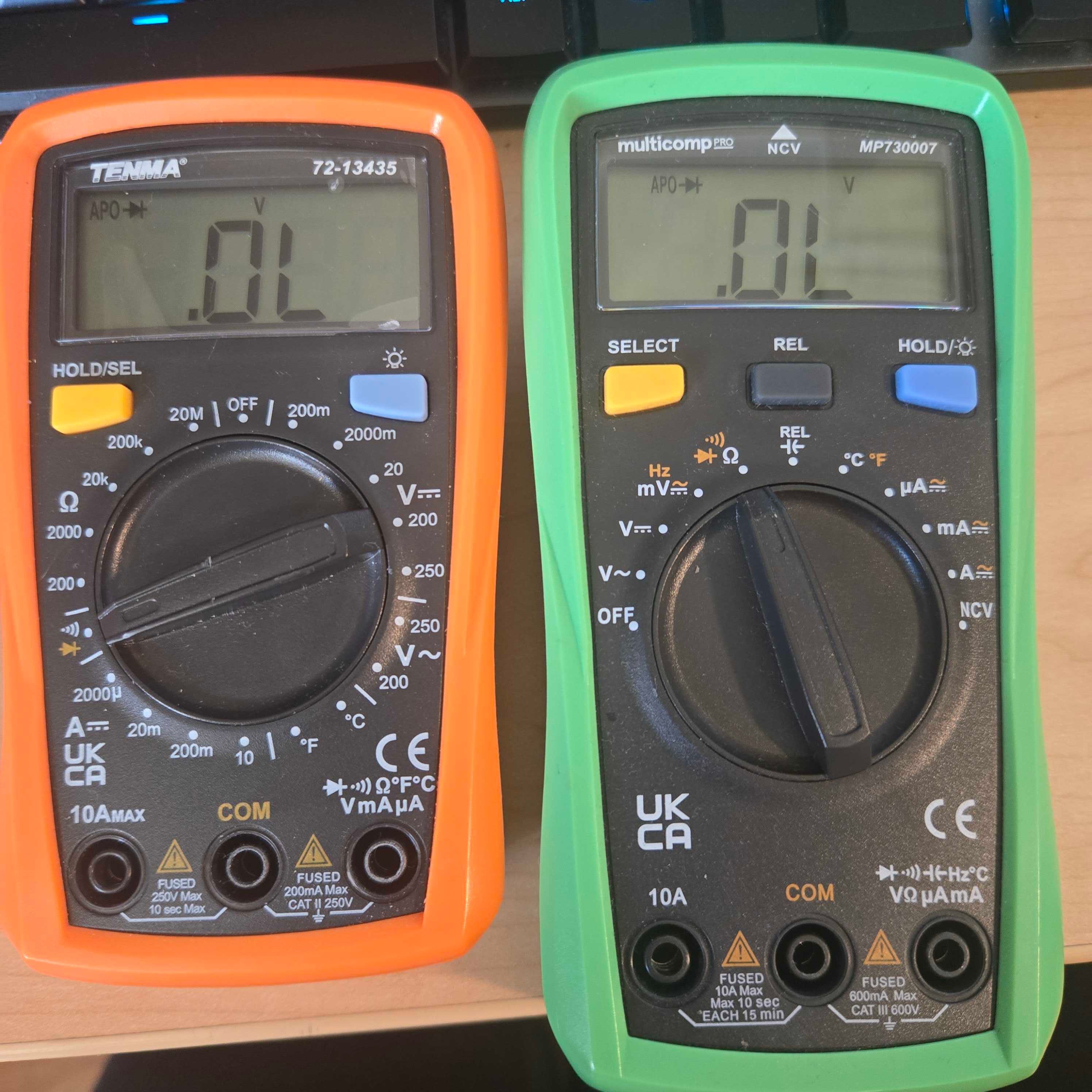
Circuits can be horribly complex beasts to debug, but more often than you might believe, the error can be chalked up to a connection issue; enter continuity testing. You may need to hit “HOLD/SELECT” a few times, but once you see the little speaker icon, your handheld will beep whenever a current could feasibly pass through whatever your two leads are connected to. This is amazingly useful for detecting unintentional shorts (direct connections, not Youtube 😔), detecting any damaged connections, either on a board or in a wire, or determing if a material is capable of conducting current (although there are ways to do this with resistance…).
Breadboard Basics
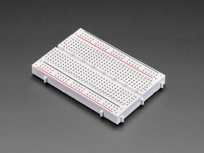
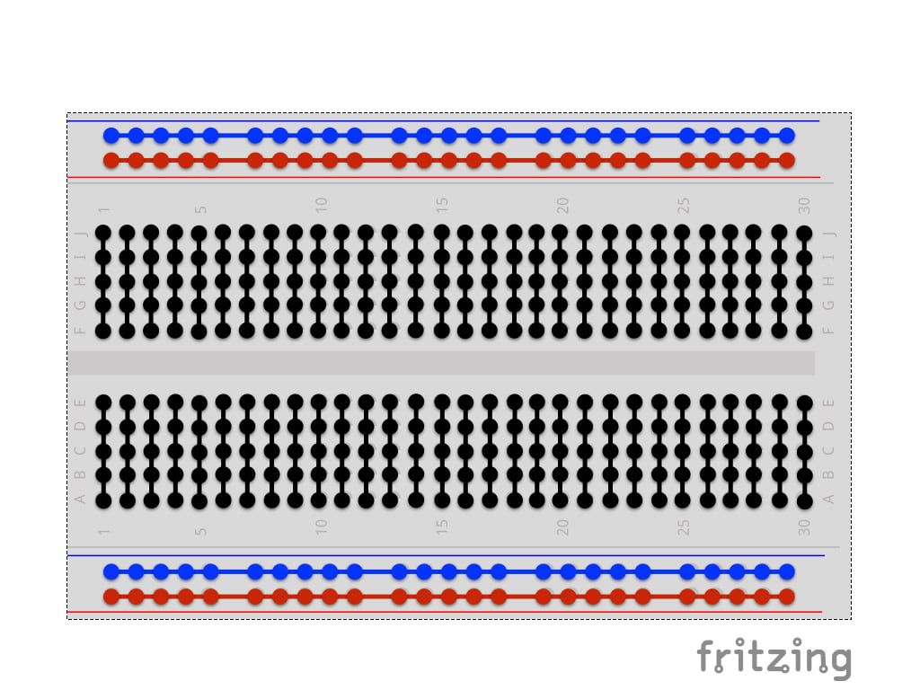
Breadboards are the baseplates of the circuits we’ll be making this week. While alternatives such as printed circuit boards (PCBs) exist, they require quite a bit of planning and forethought to use, making breadboards a simpler alternative. In the category soldered and solderless variants exist; this week, we’ll eventually use both, but for now, solderless will have to do. All one must do is press the leads of a component into the holes, and they’ll immediately stay in place, while also connecting to their assigned neighbors.
The chart below shows the specifics of these connectings, but in general, with the breadboard oriented vertically, the holes in each row are connected, but isolated from the row on the other side of the center gap. The two columns on each side, called power rails, each form their own isolated system.
Power Supplies
Power supplies are somewhat intricate devices, capable of providing a constant source of either voltage or current, while adjusting the opposite for the needs of the project. This week, we will exclusively use them as constant voltage sources.
You might have heard that current kills. Today, you hopefully learned about Ohm’s law, or , where is voltage, is current, and is resistance. As voltage will be held constant, this means that the current coming from the power supply depends on the resistance of the circuit. A bit of algebra will tell you that current and resistance vary inversely, so this week, we’ll be using higher valued resistors ranging from to (or more commonly in the field, and ). Therefore, in the smallest circuit we could make, a power source connected to a resistor, the current flowing through the circuit flowing through the circuit, , would be 0.01 amps, or more commonly, about 10mA. More commonly, however, our circuits will use on the order of magnitude of a tenth of a milliamp (or a ten-thousandth of an amp).
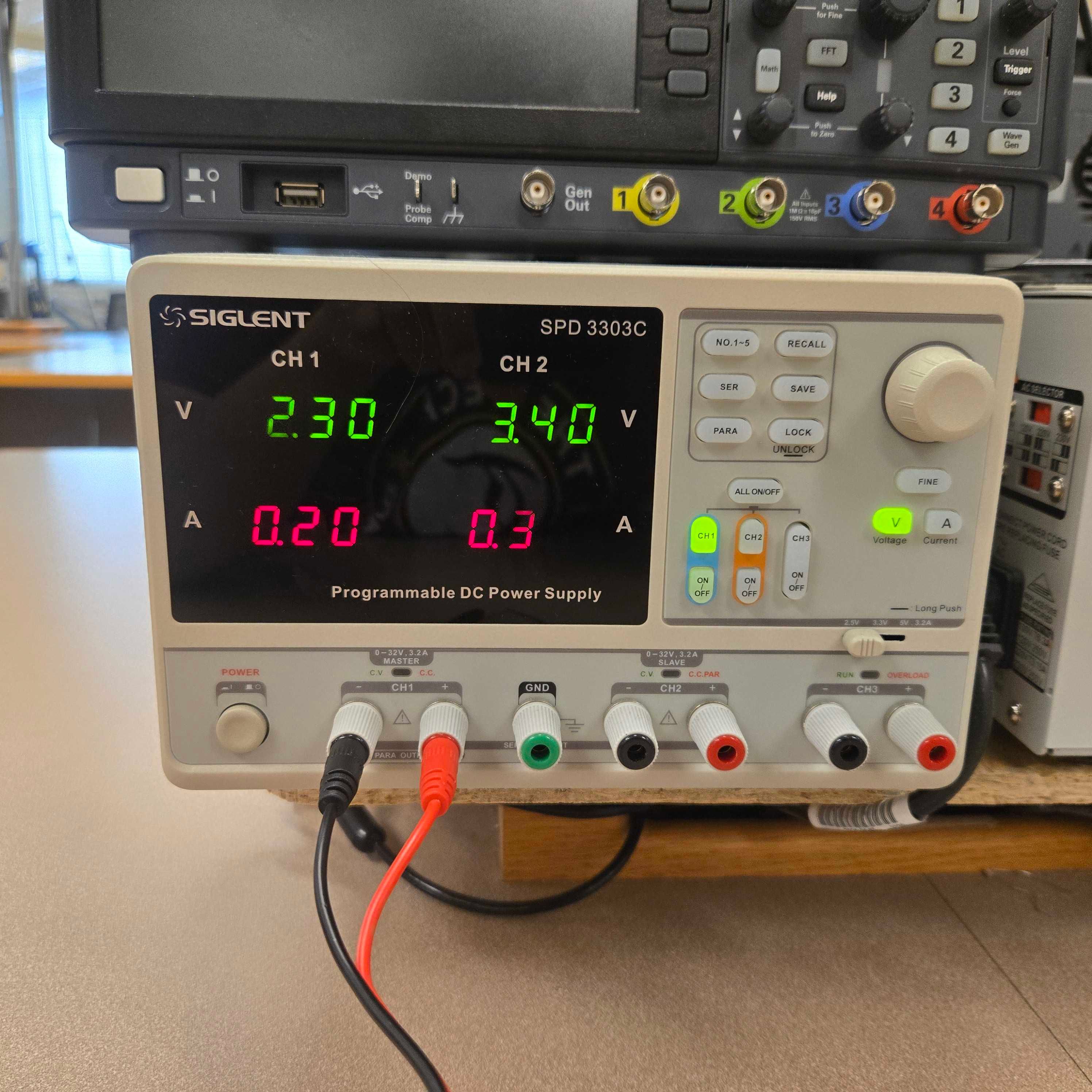
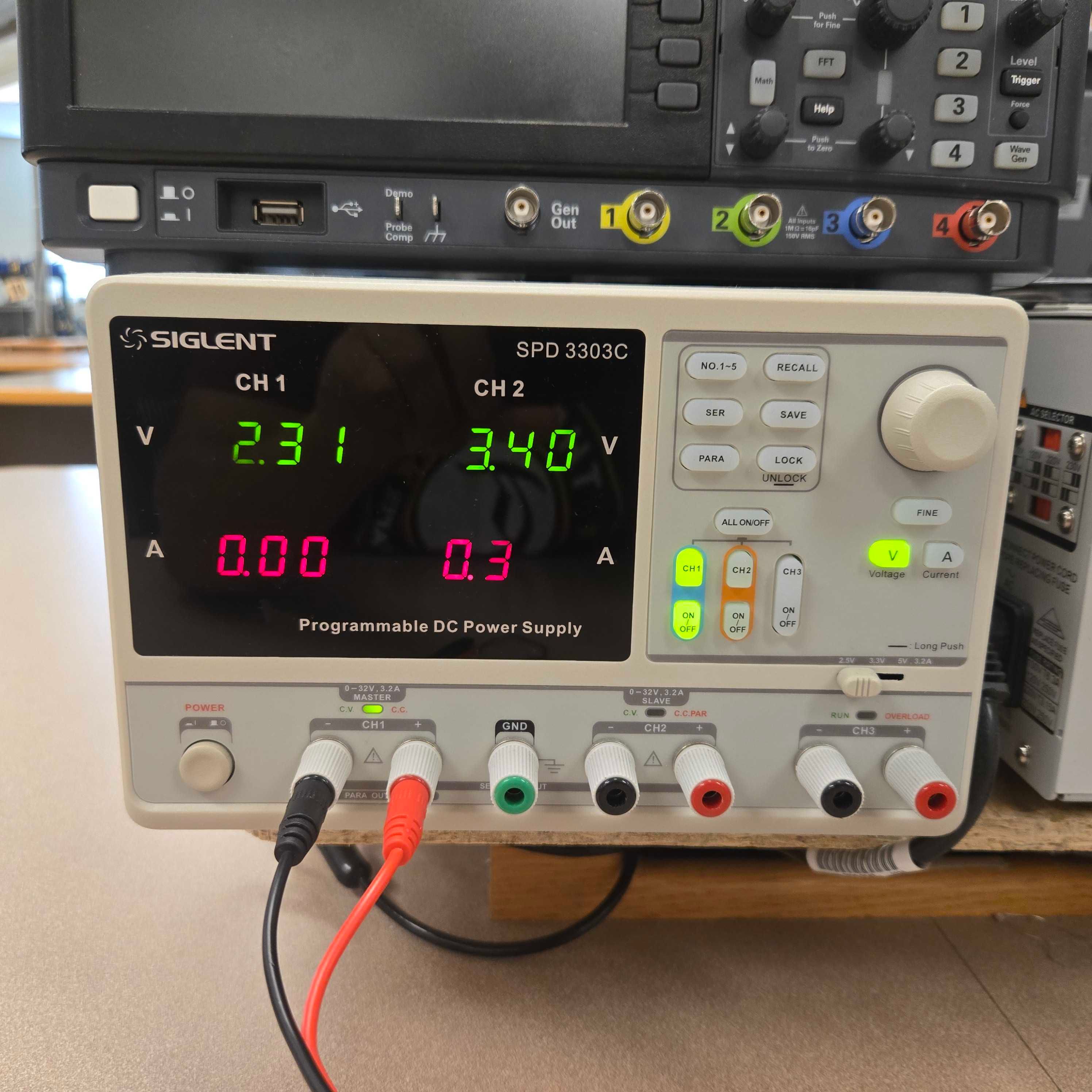
Conveniently enough, the power supplies we’ll be using this week have the ability to set their max current output. Based on the previous calculations, 0.2A should be more than sufficient for what we’re making this week, so set the limit here, and don’t hesistate to have a counselor come check it before starting.
- Press the main power button
- Click the voltage (V) button, then use the knob to set the CH 1 voltage
- Press current (A), then set to the maximum current (0.2A) with the knob
- Press voltage (V) once again to return to constant voltage mode
- Check everything again
- Press the On/Off button below the CH1 button
Beyond this, however, there are a few basic rules everyone should follow to further reduce the chances of accidents occuring:
- Always turn off your power supply when modifying your circuit, never touch exposed leads while the power supply is running.
- An extension of this is to build your circuit before ever connecting to the supply in the first place.
- Never leave your power supply unattended, and shut it off at the first sign of trouble
- Always check the connections in your circuit before powering it, checking for moisture, body parts or other personal effects coming in contact with the board, or anything that might unintentionally carry a current.