Public Archive This website won't be receiving any further updates, but will be left up in the hopes that someone may find it useful (here's the source code). Thanks to everyone who made this possible, and maybe see y'all again next year! -Colin & Titus
Casual Voltage Dividers
Now, with our tools in had, he can make one of the most basic (yet infinitely useful) circuits: The Voltage Divider
Connecting to PSU
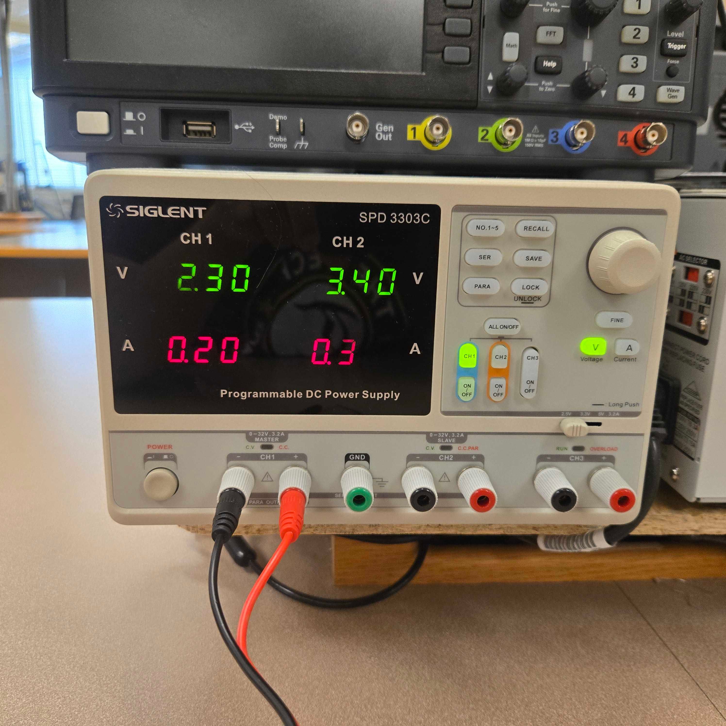
As the name would imply, we need some voltage to divide. You will need two cables, one for positive, one for negative. They attach to channel 1 on the power supply as pictured below. You may need to push them in somewhat to get them to stick.
Connecting to Board
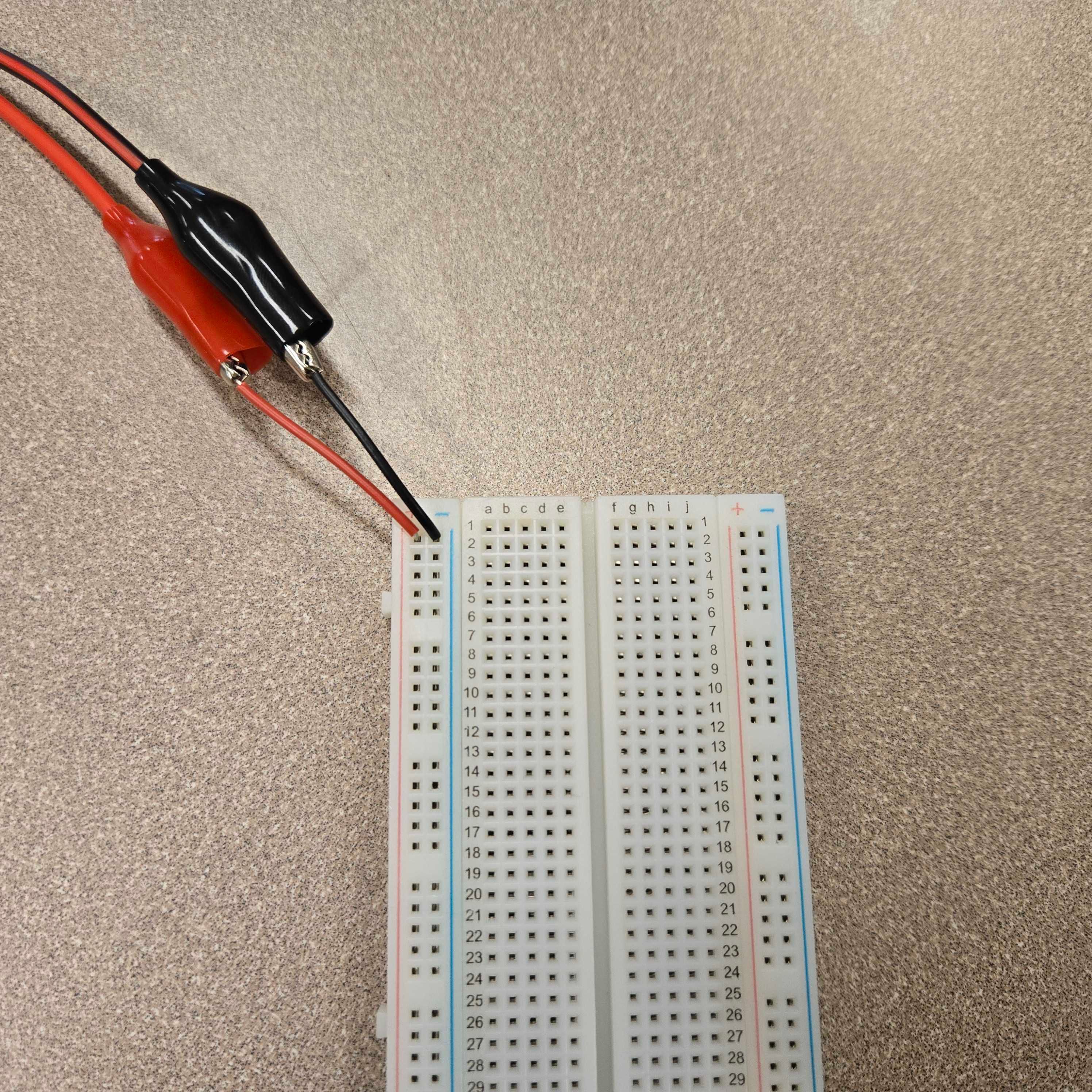
On the board side of things, we have a problem: the other ends of the cables are alligator clips, which notably don’t fit into any of the holes. You’ll have to cut two pieces of hook-up wire to create the connections, as pictured below.
Creating the Divider
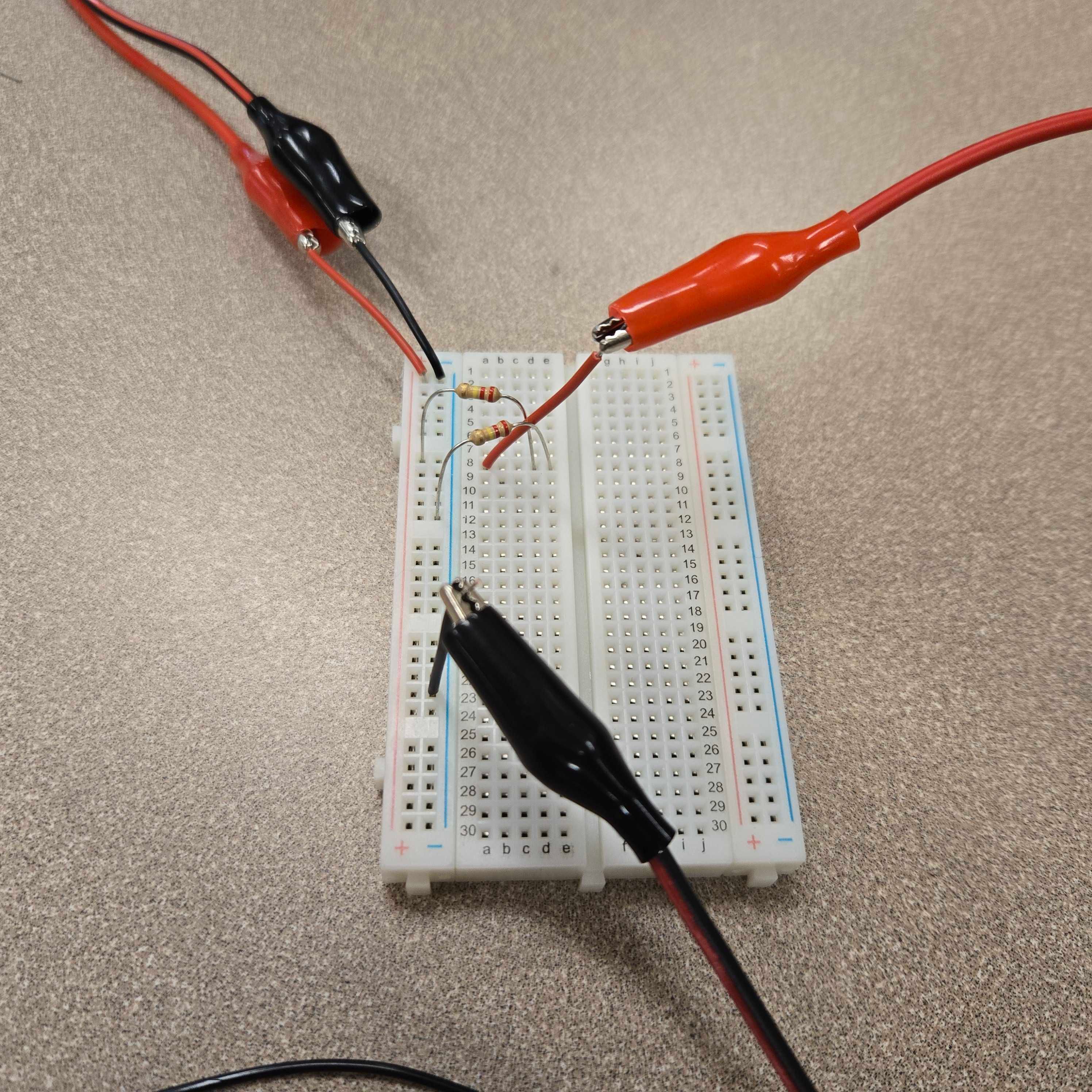
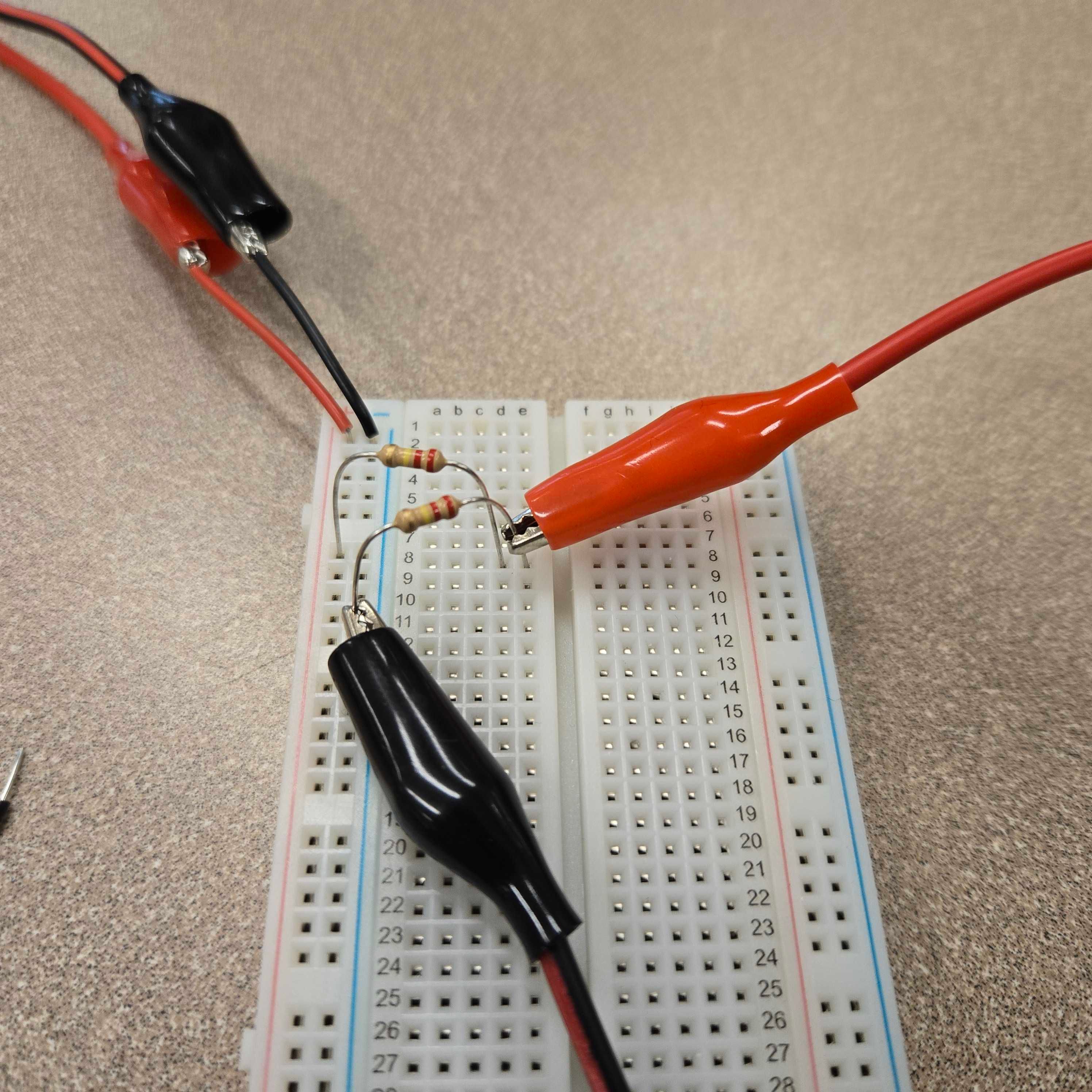
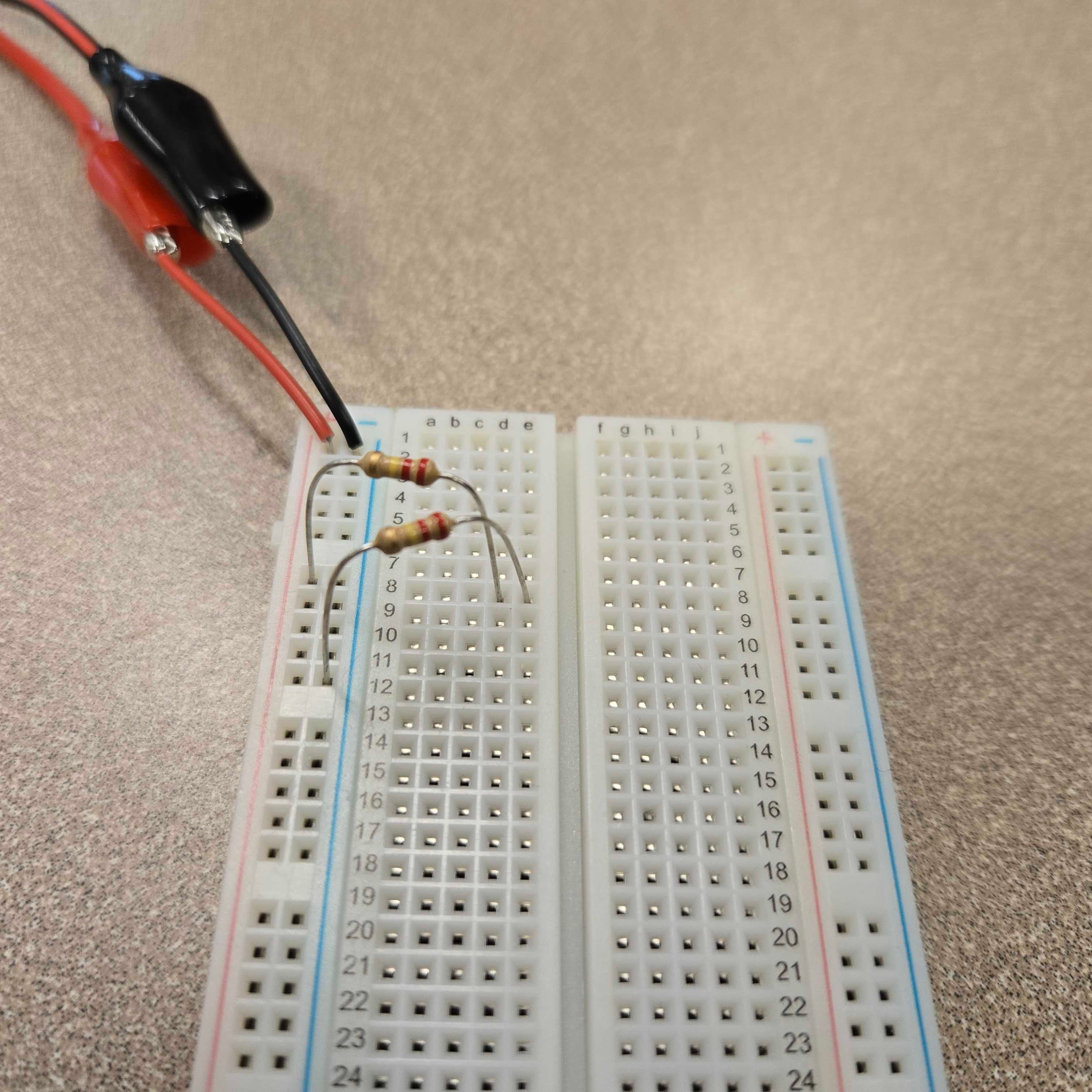
One of the easiest ways to create the divider itself is to simply connect the first resistor from a power rail to an empty row on the board, then the second from the same row to the opposite power rail, as is the case with the two resistors pictured below.
Measuring the Divider
Now that we need to measure the voltage coming from the divider, we run into the same problem with the alligator clips. You can either create connectors like with the PSU, or you can clamp onto the resistor leads directly, as pictured below.
